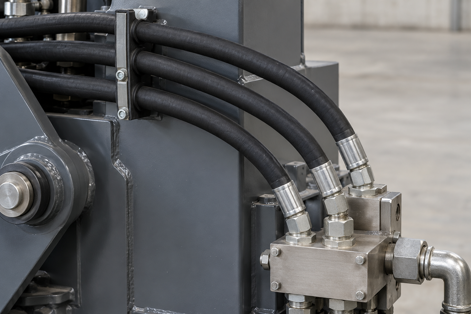
The short answerA hose can have the right bore and pressure rating yet be unsuitable for its route. Length, bend radius, end orientation, machine movement and surrounding contact points must be reviewed as one assembly.
A straight-line measurement between two ports is not the installed hose length. It omits the bends, straight sections at the ends, connection geometry and any movement the assembly must accommodate.
Bend radius is a limit, not a feel test
A hose that bends easily by hand is not automatically permitted to run around a tight radius. Bending resistance and minimum permitted bend radius describe different characteristics. Use the exact hose’s published requirement, including the stated measurement reference and the intended duty.
A radius is also not a diameter. If a drawing specifies a centreline bend radius of 150 mm, the centreline diameter of that circle is 300 mm. Do not assume that this geometric reference is the same reference used by every product’s minimum-bend specification.
| Routing feature | What the review should establish | What an extra length measurement misses |
|---|
| Bend | Radius and reference meet the selected product’s requirement. | The most constrained point can still be too tight. |
| End fitting | Bend does not start in an unsuitable place at the coupling. | More length elsewhere does not repair the end geometry. |
| Angled ends | Both ends have the specified angular orientation. | Correct total length does not remove twist. |
| Machine movement | The route is acceptable through the required movement range. | One static position may conceal the worst condition. |
| Nearby surfaces | Contact, abrasion and heat exposure are addressed. | A free-looking route can still contact a moving component. |
Comparison framework. Product-specific limits remain those of the selected manufacturer.
Separate geometric length from cut length
Worked example · illustrativeA simple half-circle in a drawing
For an illustrative centreline radius R = 150 mm, the curved centreline length of a half-circle is πR, approximately 471 mm. If the sketch also contains two 100 mm straight centreline sections, its geometric path totals approximately 671 mm.
This is a geometry exercise, not a hose cut length. Connection datums, end-fitting geometry, straight-length requirements, tolerances, pressure-related length change and movement still have to be addressed for the selected assembly.
End orientation can decide whether it fits
Two angled fittings can have the correct individual connection designations but the wrong orientation relative to one another. Show the orientation on the assembly drawing using an agreed reference. The installed hose should not be twisted to compensate for a drawing or assembly error.
Twist, sharp bending at the fitting junction and unwanted contact all need to be addressed in the routing review. A hose route is therefore an assembly definition, not just a bulk-hose specification.
Check the changing geometry
Identify the positions that create the tightest bend, greatest extension and closest approach to surrounding components. They may not be the same position. A drawing or controlled review should make those positions visible before the assembly is released.
Adding length indiscriminately can create another contact or motion problem. The objective is the right route with the right constraints, rather than the longest hose that fits inside the machine.
What belongs in the released drawing?
Keep connection identities, length datums, end angles and orientation together with the routing requirements. Identify the approved hose-and-fitting system and the relevant operating conditions. Installation and inspection should be carried out by qualified personnel under the applicable procedures.
A complete drawing allows a repeat assembly to reproduce a reviewed arrangement. A single overall length and two informal photographs often leave the most important geometric decisions to the next installer.